到目前为止,我已经看到用于边缘设备机器学习的Edge Impulse开发平台被多个开发板使用了,但我一直没有机会尝试使用它。因此,当矽递科技 (Seeed Studio)问我是否有兴趣测试由nRF52840驱动的XIAO BLE Sense 板时,我欣然答应了。我觉得使用Edge Impulse对XIAO BLE Sense板进行评测可能还不错,因为我在该板的示例中看到了动作和手势识别的测评示例。
不过,这个测评真的是一个挺大的挑战,因为从矽递科技第一次联系我,直到我完成评测,足足花了四个月的时间。很大的原因是DHL的沟通不畅导致第一批板子被海关扣留,所以浪费了大量时间。而且由于他们很不清晰的文档说明(现已修复),我花了很长一段时间才搞清楚如何使用。此外,其他的一些评测内容也影响了我。一番折腾之后,我终于让这个测评顺利进行了,接下来我们一起看看具体情况。
XIAO BLE (Sense)和OLED显示屏拆箱
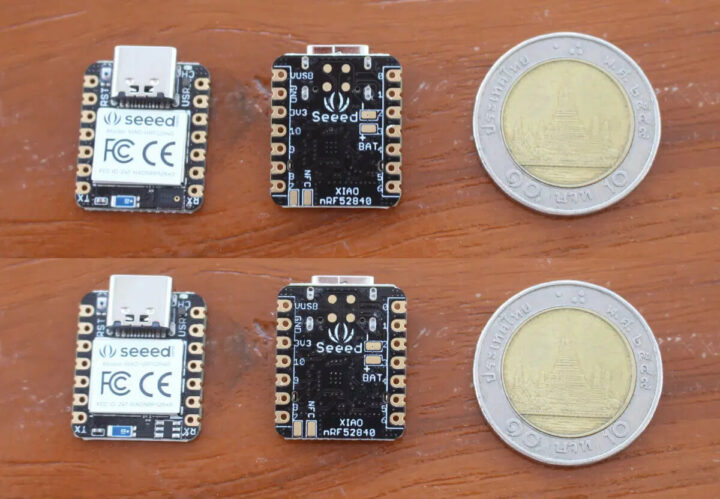
由于在手势识别的演示中他们使用到了OLED显示屏,所以我也要了一块来测试。最终,我收到了不带传感器的XIAO BLE板、XIAO BLE Sense板和Grove 0.66英寸的OLED显示屏。

这两块板都非常小,除了XIAO BLE缺少LSM6DS3TR板载6轴IMU(左下方)外,其他是完全相同的。
一些焊接
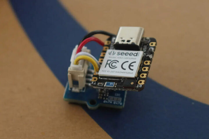
在将固件加载到主板之前,我必须将显示屏焊接到主板上。于是我剪断了Grove 电缆并将黑色和红色电线焊接到电源上,将白色和黄色电线焊接到I2C上。
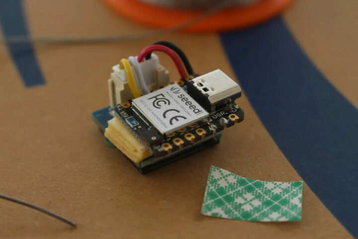
目前我暂时没有3D打印机(这又是另一个关于海关的故事了,我们还是不要扯远了),所以我使用了几层双面胶带将两块板粘在一起,这个操作其实可做可不做。
XIAO BLE Sense的OLED显示器和加速度计的Arduino项目
我花了一段时间才找到手势识别演示的说明,因为视频说明中没有列出相关的说明,我在矽递科技的wiki中也找不到任何相关信息。终于,我还是找到了说明链接,该公司修改网站后更容易找到了。
在使用Edge Impulse之前,我们将运行两个Arduino的示例用来检查OLED显示屏和加速度计,看其是否按预期工作。
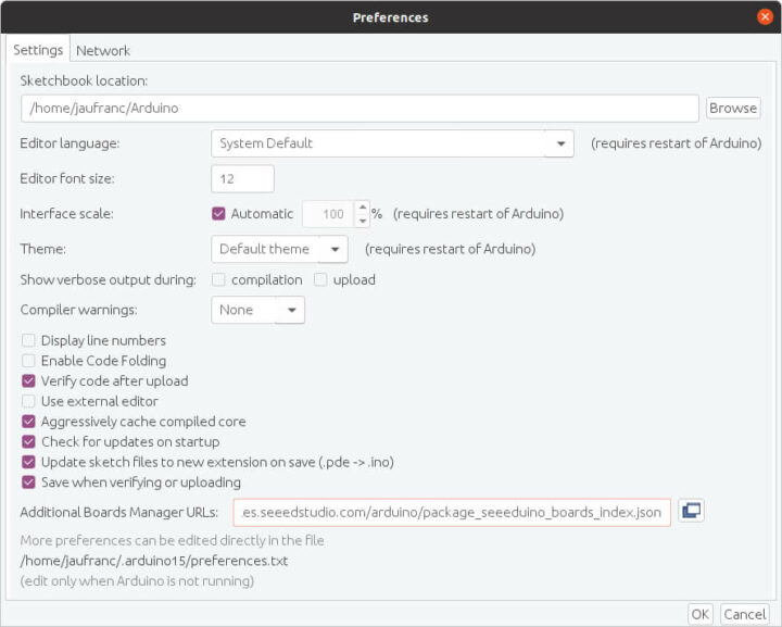
第一步是矽递科技的板子添加板管理器URL:https://files.seeedstudio.com/arduino/package_seeeduino_boards_index.json
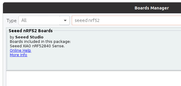
现在我们可以安装软件包来支持Seeed nRF52板了。
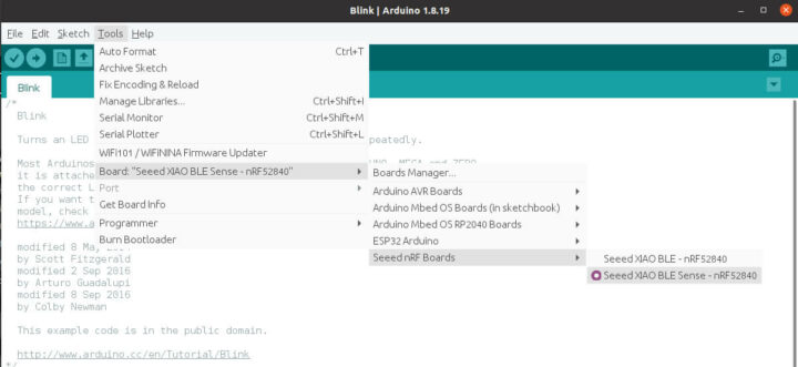
完成后,我们用Type-C电缆将开发板连接到电脑上,然后选择“Seeed XIAO BLE Sense – nRF52840”开发板,并使用默认的设置。
接下来我们尝试一个“Hello World”程序,确保我们的电路板正常工作并且与 OLED显示器正常连接。
|
1 2 3 4 5 6 7 8 9 10 11 12 13 14 15 16 17 18 19 20 21 22 23 24 |
#include <Arduino.h> #include <U8g2lib.h> #ifdef U8X8_HAVE_HW_SPI #include <SPI.h> #endif #ifdef U8X8_HAVE_HW_I2C #include <Wire.h> #endif U8G2_SSD1306_128X64_NONAME_F_SW_I2C u8g2(U8G2_R0, /* clock=*/ PIN_WIRE_SCL, /* data=*/ PIN_WIRE_SDA, /* reset=*/ U8X8_PIN_NONE); void setup(void) { u8g2.begin(); } void loop(void) { u8g2.clearBuffer(); // clear the internal memory u8g2.setFont(u8g2_font_ncenB08_tr); // choose a suitable font u8g2.drawStr(32,30,"Hello"); // write something to the internal memory u8g2.drawStr(32,45,"Seeed!"); u8g2.sendBuffer(); // transfer internal memory to the display delay(1000); } |
但是,这样操作之后并没有按预期工作,而且在编译时还出现了错误:
|
1 2 |
exec: "adafruit-nrfutil": executable file not found in $PATH Error compiling for board Seeed XIAO BLE Sense - nRF52840. |
仔细研究之后,我发现答案在Adafruit网站上,我从中了解到两个重要细节:
- nRF52需要Arduino 1.8.15或更高版本才能运行,因此可能需要升级到最新版本
- Linux需要安装adafruit-nrfutil
由于我使用的是Ubuntu 20.04,我必须要运行如下内容:
|
1 2 |
pip3 install --user adafruit-nrfutil export PATH=:$PATH:$HOME/.local/bin |
注意,如果你在Windows或MacOS中使用Arduino IDE,那么就不需要这样做了。该实用程序可以安装在$HOME/.local/bin中,因此你需要将其添加到你的路径中,然后重新启动Arduino IDE。这一步也可以临时在命令行中完成:
|
1 |
export PATH=:$PATH:$HOME/.local/bin |
或者也可以更改/etc/environment或~/.bashrc文件,帮助将文件夹永久添加到自己的PATH中。在其示例上就可以很好构建了,而且二进制文件烧录到板上时也没有什么问题。
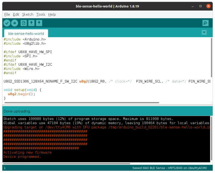
但显示屏上什么也没显示。所以我只好在主循环中添加了一个serial.println调试消息帮助检查它到底是不是在运行的。我还用万用表仔细检查了连接,但我找不到任何明显的解决方案。矽递科技让我将Seeed nRF52 Boards包降级到1.0.0 版本试试。
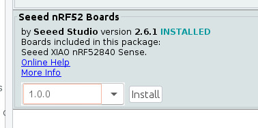
这样做之后,真的成功了!
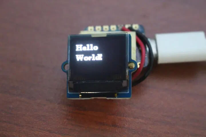
注意,在接下来的评测中,就不需要再降级到1.0.0版本了,我个人建议使用 2.6.1及以上的版本。新的“Hello World”示例如下所示:
|
1 2 3 4 5 6 7 8 9 10 11 12 13 14 15 16 |
#include <Arduino.h> #include <U8x8lib.h> U8X8_SSD1306_64X48_ER_HW_I2C u8x8(/* reset=*/ U8X8_PIN_NONE); void setup(void) { u8x8.begin(); } void loop(void) { u8x8.setFont(u8x8_font_amstrad_cpc_extended_r); u8x8.drawString(0,0,"idle"); u8x8.drawString(0,1,"left"); u8x8.drawString(0,2,"right"); u8x8.drawString(0,3,"up&down"); } |
这个时候就该切换到测试加速度计的相关演示了。首先,我们需要安装Seeed Arduino LSM6DS3库。

注意,还有一个官方的Arduino_LSM6DS3,所以可能需要卸载它才能避免冲突。下面这是代码:
|
1 2 3 4 5 6 7 8 9 10 11 12 13 14 15 16 17 18 19 20 21 22 23 24 25 26 27 28 29 30 31 32 33 34 35 36 |
#include "LSM6DS3.h" #include "Wire.h" //Create a instance of class LSM6DS3 LSM6DS3 myIMU(I2C_MODE, 0x6A); //I2C device address 0x6A #define CONVERT_G_TO_MS2 9.80665f #define FREQUENCY_HZ 50 #define INTERVAL_MS (1000 / (FREQUENCY_HZ + 1)) static unsigned long last_interval_ms = 0; void setup() { // put your setup code here, to run once: Serial.begin(115200); while (!Serial); //Call .begin() to configure the IMUs if (myIMU.begin() != 0) { Serial.println("Device error"); } else { Serial.println("Device OK!"); } } void loop() { if (millis() > last_interval_ms + INTERVAL_MS) { last_interval_ms = millis(); Serial.print(myIMU.readFloatGyroX() * CONVERT_G_TO_MS2,4); Serial.print('\t'); Serial.print(myIMU.readFloatGyroY() * CONVERT_G_TO_MS2,4); Serial.print('\t'); Serial.println(myIMU.readFloatGyroZ() * CONVERT_G_TO_MS2,4); } } |
注意,当我将Seeed nRF52 Boards v1.0.0与该示例一起使用时,我会收到“解码错误”的消息,但该消息在版本2.6.1中就消失了。我们需要打开串行监视器来检查一下X、Y、Z值是否显示。
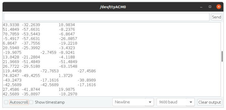
这里有一个重要提示:下一步我们仍然需要运行加速度器示例。因此,如果一开始使用了其他示例,也要确保加速度器能正常运行,然后再切换到Edge Impulse。
在Edge Impulse上运行XIAO BLE Sense
现在了解到我们的硬件是按预期工作的,那么我们就从Edge Impulse Studio开始吧。我们注册并构建第一个项目。

我们选择加速度计数据。
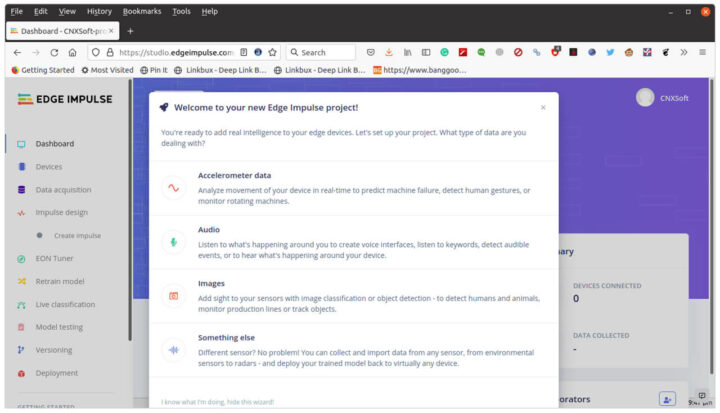
我们还需要在Linux中安装Edge Impulse CLI(本次评测我使用的是Ubuntu 20.04),首先需要安装NodeJS 14.x:
|
1 2 |
curl -sL https://deb.nodesource.com/setup_14.x | sudo -E bash - sudo apt install -y nodejs |
默认目录将会在/usr ,而且只能以root访问,所以我要将其更改为一个用户的目录,我还将其添加到了我们的路径中:
|
1 2 3 |
mkdir ~/.npm-global npm config set prefix '~/.npm-global' echo 'export PATH=~/.npm-global/bin:$PATH' >> ~/.bashrc |
现在可以安装Edge Impulse CLI:
|
1 |
npm install -g edge-impulse-cli |
这里可能需要退出终端并重新启动它,才能应用新的PATH。现在我们可以启动 Edge-impulse-data-forwarder用于非Edge Impulse官方支持的板,比如:XIAO BLE Sense:
|
1 2 3 4 5 6 7 8 9 10 11 12 13 14 15 16 17 18 19 |
$ edge-impulse-data-forwarder Edge Impulse data forwarder v1.14.12 Endpoints: Websocket: wss://remote-mgmt.edgeimpulse.com API: https://studio.edgeimpulse.com/v1 Ingestion: https://ingestion.edgeimpulse.com [SER] Connecting to /dev/ttyACM0 [SER] Serial is connected (5B:5B:83:F3:C6:0A:0C:DD) [WS ] Connecting to wss://remote-mgmt.edgeimpulse.com [WS ] Connected to wss://remote-mgmt.edgeimpulse.com [SER] Detecting data frequency... [SER] Detected data frequency: 50Hz ? 3 sensor axes detected (example values: [10.9834,-15.7887,-4.8053]). What do y ou want to call them? Separate the names with ',': Ax, Ay, Az ? What name do you want to give this device? XIAO BLE SENSE [WS ] Device "XIAO BLE SENSE" is now connected to project "XIAO BLE Sense motion detection" [WS ] Go to https://studio.edgeimpulse.com/studio/91558/acquisition/training to build your machine learning model! |
第一次运行命令时,需要输入用户名和密码(上面未显示)。该应用程序扫描串行设备,连接到Edge Impulse,然后需要尝试检测来自串行端口的数据,一旦完成,系统会要求我们命名数据字段(Ax,Ay,Az),设备(XIAO BLE SENSE),将自动添加它到我们刚刚创建的项目当中。如果Edge Impulse中有多个项目,系统会要求你先选择项目名称。这意味着它基本上与硬件无关,只要你的电路板将加速度计数据输出到串行接口,它应该就可以工作。
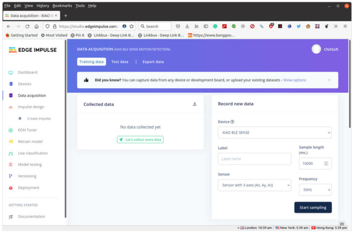
现在我们回到Edge Impulse,点击Data acquisition,会看到我们的设备以及传感器参数和数据频率设置。
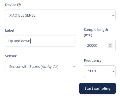
我将样本大小设置为20,000 ms、定义一个标签、单击Start Sampling,然后以大约1秒的间隔,上下移动电路板20秒,通过这样的方式来获取数据。

然后,我们需要通过单击原始部分中的三个点并选择“Split Sample”来拆分数据。单击“+Add Segment”添加更多部分。我们应该这样重复它,直到我们有大约20个代表上下运动的片段。如果你的移动速度慢于或快于1秒,请在“Set segment length (ms.)”中调整时间。
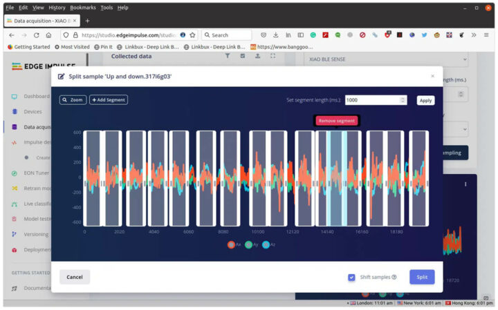
我使用的是火狐,这里我遇到了一个奇怪的错误,我可以添加一个segment,但是当我选择并移动它时,它会向右偏移一个偏移量,有时甚至在屏幕之外。但是,如果我一直按住鼠标按钮,然后向左移动,它又可能会重新出现在视野中。这真的不太方便,而且我不能放大太多,否则盒状图形有太多会从显示屏上消失。我想将Chrome或Microsoft Edge与Edge Impulse结合使用可能会更好。
单击Split后,我们将回看到我们选择的1秒数据样本。
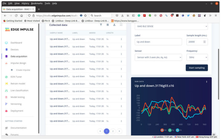
我们可以重复数据采集和拆分其他的手势,比如左、右、顺时针旋转和逆时针旋转。我建议还是先从简单的开始,我们将在下面看到。
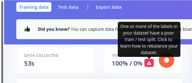
此时,你可能会看到带有警告的数据,看起来好像有点问题:
数据收集中的一个或多个标签的测试性能不佳
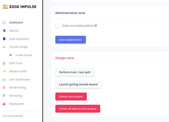
要解决这个问题,可以通过单击左侧菜单中的“仪表板”并向下滚动来找到“执行测试/测试拆分”按钮来捕获较短时间(例如2秒)的测试数据,或重新平衡数据集。
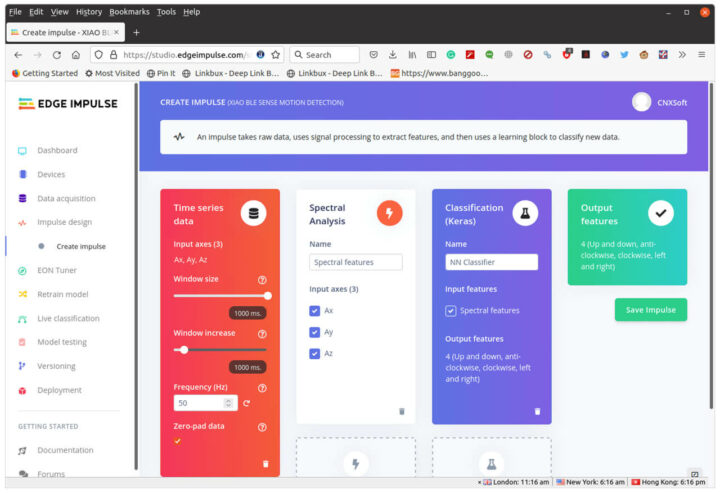
现在我们准备好创建一个impulse。单击创建impulse -> 添加处理块 -> 选择光谱分析 -> 添加学习块 -> 选择分类 (Keras) -> 保存impulse。
在Spectral Analysis中单击Spectral features,然后单击Save parameters和Generate features。
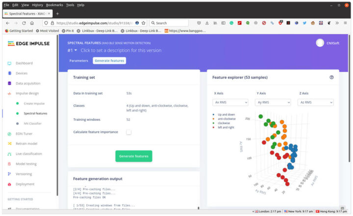
我们可能希望数据被清晰地分开,但很显然还有一些重叠,因此测试的数据并不如我们想象的理想。尽管如此,我还是打算继续尝试。
单击NN Classifier,然后单击“Start training”,这大约需要1分钟的时间来处理。然后我们可以选择Unoptimized(float32)。
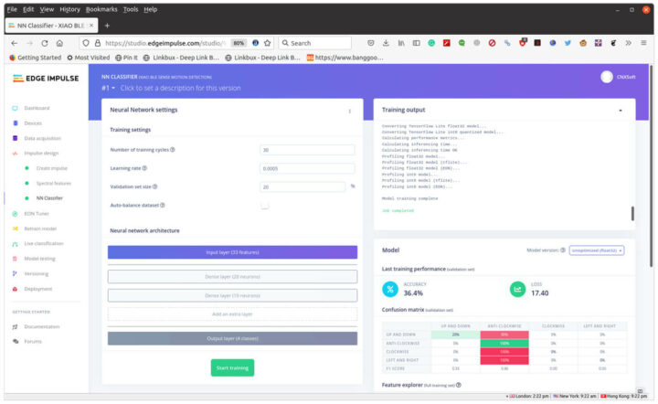
这么看来准确率确实很低,模块基本上无法使用,只有“逆时针”被正确检测到。
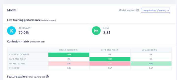
我们再试一次,只有上下、左右和圆圈(顺时针),我也试图将每个动作保持在一秒钟内。
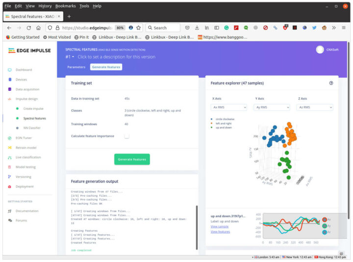
在浏览器图表中,蓝色、橙色和绿色的圆点位于各自的区域,这样看起来确实更好一些。我们也可以删除一些可能出现问题的结果。测试后的结果并不完美,但我们还是可以尝试一下。
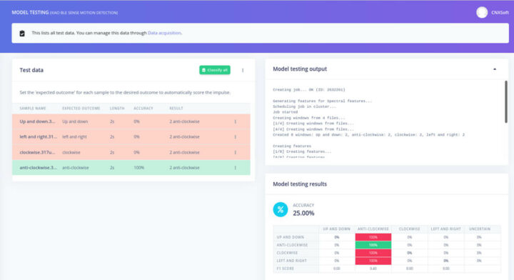
我们试试左侧菜单中的“模块测试”。
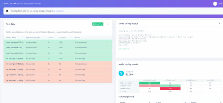
这真的有点令人失望,因为只有顺时针方向的转圈效果很好,“左和右模拟时”大约只有一半的时间可以被检测到,“上下模拟时”则被错误地检测为左和右。所以这么看来除了训练数据之外,还必须把操作员也训练一下。
比较重要的部分是创建impulse的方法,随着时间的推移,我们应该能够创建更好的数据。我们通过单击左侧菜单中的Deployment来构建Arduino库,然后单击Arduino Library、 Build,最后下载.ZIP文件。
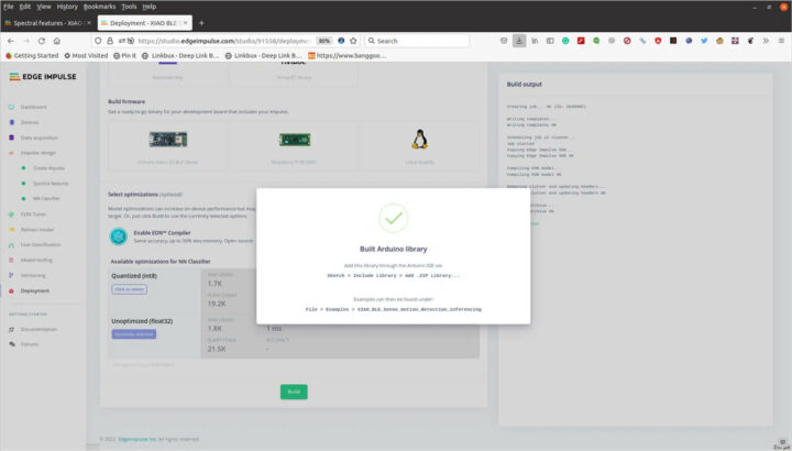
回到Arduino IDE,先下载矽递科技提供的Arduino示例,注意该示例在过去几个月中经过了很多次修改。在这里我们需要更改Edge Impulse的头文件(下面示例中的第24行)来匹配自己的,我还必须使用U8X8lib.h库注释掉该行。我还稍微修改了代码,因为我没有像在他们的演示中那样去测试“空闲时”的状态:
|
1 2 3 4 5 6 7 8 9 10 11 12 13 14 15 16 17 18 19 20 21 22 23 24 25 26 27 28 29 30 31 32 33 34 35 36 37 38 39 40 41 42 43 44 45 46 47 48 49 50 51 52 53 54 55 56 57 58 59 60 61 62 63 64 65 66 67 68 69 70 71 72 73 74 75 76 77 78 79 80 81 82 83 84 85 86 87 88 89 90 91 92 93 94 95 96 97 98 99 100 101 102 103 104 105 106 107 108 109 110 111 112 113 114 115 116 117 118 119 120 121 122 123 124 125 126 127 128 129 130 131 132 133 134 135 136 137 138 139 140 141 142 143 144 145 146 147 148 149 150 151 152 153 154 155 156 157 158 159 160 161 162 163 164 165 166 167 168 169 170 171 172 173 174 175 176 177 178 179 180 181 182 183 184 185 186 187 188 189 190 191 192 193 194 195 196 197 |
/* Edge Impulse Arduino examples * Copyright (c) 2021 EdgeImpulse Inc. * * Permission is hereby granted, free of charge, to any person obtaining a copy * of this software and associated documentation files (the "Software"), to deal * in the Software without restriction, including without limitation the rights * to use, copy, modify, merge, publish, distribute, sublicense, and/or sell * copies of the Software, and to permit persons to whom the Software is * furnished to do so, subject to the following conditions: * * The above copyright notice and this permission notice shall be included in * all copies or substantial portions of the Software. * * THE SOFTWARE IS PROVIDED "AS IS", WITHOUT WARRANTY OF ANY KIND, EXPRESS OR * IMPLIED, INCLUDING BUT NOT LIMITED TO THE WARRANTIES OF MERCHANTABILITY, * FITNESS FOR A PARTICULAR PURPOSE AND NONINFRINGEMENT. IN NO EVENT SHALL THE * AUTHORS OR COPYRIGHT HOLDERS BE LIABLE FOR ANY CLAIM, DAMAGES OR OTHER * LIABILITY, WHETHER IN AN ACTION OF CONTRACT, TORT OR OTHERWISE, ARISING FROM, * OUT OF OR IN CONNECTION WITH THE SOFTWARE OR THE USE OR OTHER DEALINGS IN THE * SOFTWARE. */ /* Includes ---------------------------------------------------------------- */ #include <XIAO_BLE_Sense_motion_detection_inferencing.h> #include <LSM6DS3.h> #include <U8g2lib.h> // #include <U8X8lib.h> #include <Wire.h> /* Constant defines -------------------------------------------------------- */ #define CONVERT_G_TO_MS2 9.80665f #define MAX_ACCEPTED_RANGE 2.0f // starting 03/2022, models are generated setting range to +-2, but this example use Arudino library which set range to +-4g. If you are using an older model, ignore this value and use 4.0f instead /* ** NOTE: If you run into TFLite arena allocation issue. ** ** This may be due to may dynamic memory fragmentation. ** Try defining "-DEI_CLASSIFIER_ALLOCATION_STATIC" in boards.local.txt (create ** if it doesn't exist) and copy this file to ** `<ARDUINO_CORE_INSTALL_PATH>/arduino/hardware/<mbed_core>/<core_version>/`. ** ** See ** (https://support.arduino.cc/hc/en-us/articles/360012076960-Where-are-the-installed-cores-located-) ** to find where Arduino installs cores on your machine. ** ** If the problem persists then there's not enough memory for this model and application. */ U8X8_SSD1306_64X48_ER_HW_I2C u8x8(/* reset=*/ U8X8_PIN_NONE); /* Private variables ------------------------------------------------------- */ static bool debug_nn = false; // Set this to true to see e.g. features generated from the raw signal LSM6DS3 myIMU(I2C_MODE, 0x6A); /** * @brief Arduino setup function */ const int RED_ledPin = 11; const int BLUE_ledPin = 12; const int GREEN_ledPin = 13; void setup() { // put your setup code here, to run once: Serial.begin(115200); //u8g2.begin(); u8x8.begin(); Serial.println("Edge Impulse Inferencing Demo"); //if (!IMU.begin()) { if (!myIMU.begin()) { ei_printf("Failed to initialize IMU!\r\n"); } else { ei_printf("IMU initialized\r\n"); } if (EI_CLASSIFIER_RAW_SAMPLES_PER_FRAME != 3) { ei_printf("ERR: EI_CLASSIFIER_RAW_SAMPLES_PER_FRAME should be equal to 3 (the 3 sensor axes)\n"); return; } } /** * @brief Return the sign of the number * * @param number * @return int 1 if positive (or 0) -1 if negative */ float ei_get_sign(float number) { return (number >= 0.0) ? 1.0 : -1.0; } /** * @brief Get data and run inferencing * * @param[in] debug Get debug info if true */ void loop() { u8x8.clear(); u8x8.setFont(u8g2_font_ncenB08_tr); ei_printf("\nStarting inferencing in 2 seconds...\n"); delay(2000); ei_printf("Sampling...\n"); // Allocate a buffer here for the values we'll read from the IMU float buffer[EI_CLASSIFIER_DSP_INPUT_FRAME_SIZE] = { 0 }; for (size_t ix = 0; ix < EI_CLASSIFIER_DSP_INPUT_FRAME_SIZE; ix += 3) { // Determine the next tick (and then sleep later) uint64_t next_tick = micros() + (EI_CLASSIFIER_INTERVAL_MS * 1000); buffer[ix] = myIMU.readFloatAccelX(); buffer[ix+1] = myIMU.readFloatAccelY(); buffer[ix+2] = myIMU.readFloatAccelZ(); for (int i = 0; i < 3; i++) { if (fabs(buffer[ix + i]) > MAX_ACCEPTED_RANGE) { buffer[ix + i] = ei_get_sign(buffer[ix + i]) * MAX_ACCEPTED_RANGE; } } buffer[ix + 0] *= CONVERT_G_TO_MS2; buffer[ix + 1] *= CONVERT_G_TO_MS2; buffer[ix + 2] *= CONVERT_G_TO_MS2; delayMicroseconds(next_tick - micros()); } // Turn the raw buffer in a signal which we can the classify signal_t signal; int err = numpy::signal_from_buffer(buffer, EI_CLASSIFIER_DSP_INPUT_FRAME_SIZE, &signal); if (err != 0) { ei_printf("Failed to create signal from buffer (%d)\n", err); return; } // Run the classifier ei_impulse_result_t result = { 0 }; err = run_classifier(&signal, &result, debug_nn); if (err != EI_IMPULSE_OK) { ei_printf("ERR: Failed to run classifier (%d)\n", err); return; } // print the predictions ei_printf("Predictions "); ei_printf("(DSP: %d ms., Classification: %d ms., Anomaly: %d ms.)", result.timing.dsp, result.timing.classification, result.timing.anomaly); ei_printf(": \n"); for (size_t ix = 0; ix < EI_CLASSIFIER_LABEL_COUNT; ix++) { ei_printf(" %s: %.5f\n", result.classification[ix].label, result.classification[ix].value); } #if EI_CLASSIFIER_HAS_ANOMALY == 1 ei_printf(" anomaly score: %.3f\n", result.anomaly); #endif if (result.classification[0].value > 0.5) { digitalWrite(RED_ledPin, LOW); digitalWrite(BLUE_ledPin, HIGH); // circle red digitalWrite(GREEN_ledPin, HIGH); u8x8.setFont(u8x8_font_amstrad_cpc_extended_r); u8x8.drawString(1,2,"Circle"); u8x8.refreshDisplay(); delay(2000); } else if (result.classification[1].value > 0.5) { digitalWrite(RED_ledPin, HIGH); //left&right blue digitalWrite(BLUE_ledPin, LOW); digitalWrite(GREEN_ledPin, HIGH); u8x8.setFont(u8x8_font_amstrad_cpc_extended_r); u8x8.drawString(2,3,"left"); u8x8.drawString(2,4,"right"); u8x8.refreshDisplay(); delay(2000); } else if (result.classification[2].value > 0.5) { digitalWrite(RED_ledPin, HIGH); digitalWrite(BLUE_ledPin, HIGH); digitalWrite(GREEN_ledPin, LOW); //up&down green u8x8.setFont(u8x8_font_amstrad_cpc_extended_r); u8x8.drawString(2,3,"up"); u8x8.drawString(2,4,"down"); u8x8.refreshDisplay(); delay(2000); } else { digitalWrite(RED_ledPin, LOW); digitalWrite(BLUE_ledPin, LOW); digitalWrite(GREEN_ledPin, LOW); //idle off LEDs off u8x8.setFont(u8x8_font_amstrad_cpc_extended_r); u8x8.drawString(2,3,"idle"); u8x8.refreshDisplay(); delay(2000); } } |
在这里我们还需要将刚刚从Edge Impulse下载的ZIP库添加到Arduino库中,现在我们可以构建代码并将其烧录到板上。第一次大约需要5分钟,后续构建大约需要2分钟。
下面这是串口的输出。
|
1 2 3 4 5 6 7 8 9 10 11 12 13 14 15 16 17 18 19 20 |
Starting inferencing in 2 seconds... Sampling... Predictions (DSP: 10 ms., Classification: 0 ms., Anomaly: 0 ms.): circle clockwise: 0.59337 left and right: 0.14814 up and down: 0.25850 Starting inferencing in 2 seconds... Sampling... Predictions (DSP: 10 ms., Classification: 0 ms., Anomaly: 0 ms.): circle clockwise: 0.35315 left and right: 0.30938 up and down: 0.33747 Starting inferencing in 2 seconds... Sampling... Predictions (DSP: 10 ms., Classification: 0 ms., Anomaly: 0 ms.): circle clockwise: 0.67348 left and right: 0.09551 up and down: 0.23102 |
因此,每当一个值超过50时,它就会显示相应的文本,例如Circle,如果没有一个结果超过50,程序只会显示“Idle”。
你们可以看看它在视频中的样子,相关视频链接,点击此处可查看。
转圈手势被识别到了,即使我在视频中做错了,但还是能看到。但“左右识别”我只看到了几次,“上下”甚至都没有。因此,还是需要一些时间来进行适当的演示,其中重要的部分是数据采集和准确拆分,这样能确保特定手势的所有样本看起来大致相同。
最后,十分感谢矽递科技寄给XIAO BLE (Sense)板和Grove OLED显示器。不过,还是希望他们能尽快输出正确的文档。如果你们对它感兴趣,可以考虑复制上面的示例试试。
价格方面,XIAO BLE Sense板现在的售价是15.99美元,OLED显示屏的售价 是5.5美元,不过OLED显示屏是可选的,我们也可以直接在串行终端中看结果,所以主要取决于个人需要。

文章翻译者:Nicholas,技术支持工程师、瑞科慧联(RAK)高级工程师,深耕嵌入式开发技术、物联网行业多年,拥有丰富的行业经验和新颖独到的眼光!
